Date posted: November 18, 2009
- Combat! Part 1 – Parts and Plans
- Combat! Part 2 – Tips and Tweaks
- H-Frame and Combat Hits
- Combat: Reloaded – The Mach One Combat Flyer
– Download Combat! Part 1 – Parts and Plans as PDF –
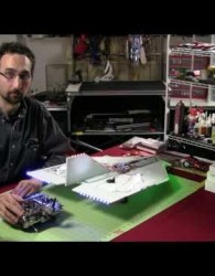
Here’s our video, with the article details and pictures following below:
Introduction
Back in the spring of 2009, my father and I went to fly our helicopters at Hobby TownUSA’s indoor track in Omaha, Nebraska. We were the only one’s there, save for a couple of gentlemen working on some RC cars. Passing by and giving some cordial ‘Hellos’ and ‘How’s it goings’, my father and I started to unload our models and see what damage we could do in our first weeks in this hobby.
One of the gentlemen came over to our bench to see what we were planning on (unintentionally) destroying that day. My father and I brought our Park Zone Vapor airplanes, my father’s CX2, and my Blade 400 helicopter. At this time, only having gone through some simple spin up and hovering exercises and hovers with my Blade 400, I was a bit nervous about trying to really get it up and off the ground without making little pieces of helicopter.
This curious gentlemen introduced himself as Frank, and our dialogue started with our explaining what complete novices we were and how we decided to try some things indoors and away from wind for easier practice. When I brought out my ‘big-gun’, the Blade 400, Frank offered to assist me in my first real hover practice. From the constant pointers of ‘More Throttle!’ ‘Keep your tail straight’, ‘More right cyclic’ and the best tip yet ‘BREATHE!’, Frank was a tremendous help in getting me to really feel how the helicopter was going to react as well as learning how to anticipate the movement of the helicopter. The anticipation of how it’s going to move, and learning to be pro-active in your stick movements instead of purely reactive.
It was this time I realized that Frank (who we’ll reference as Chameleon…he preferred this to ‘Truckin’ Frank’) was really an onion in disguise. Not that he made my eyes water and I felt a sudden urge to saute him on a frying pan…Frank is simply layers and layers of vast RC experience. After curious interrogation, we learned that Frank has not only an RC Car enthusiast, but one of helicopters and airplanes as well. He told us stories about some of the other people he’s met in his travels, different models he’s flown and built, and then of course…. COMBAT. Building cheap flyers that do nothing more than fly into other cheap flyers (or alone, if you’re enemy is the ground).
After some more lessons, practice flights, and great conversation, we exchanged contact information with Frank and parted ways. It was pure luck that we met him that day, within the next 36 hours Frank would be out of the state and across the country. The Chameleon is a truck driver, and when he’s stopped in a city for a day or so, he generally hits the local hobby shops and works on his RC cars, meeting people like my father and myself. What started out as a chance meeting has turned into regular e-mails and phone calls, me playing the role of sponge, with enough information and experience pouring out of Frank that sometimes I feel like Linda Blair with a full on case of the head-spins.
Within the next month of our first meeting, Frank shared his designs for combat delta-wing flyers that he and his friends used to fly years back. As much as he has taught me on the construction, there’s always theory behind it, introducing the concepts of lifting surfaces, dihedral, incidence angles, etc. After having gone through our own building process through Frank’s emails and phone calls, I wanted to record this on Hover and Smile for posterity’s sake. Not only has it given my father and I a great project to work on together while Frank is trucking away across the country, but it’s been an excellent learning experience.
We hereby present Chameleon’s design on Hover and Smile through our building and flying experience, and since I’m a novice at this, I hope it shows you how relatively easy it is to build one…or two….or three. If nothing else, it may give you some … thoughts and ideas.
It’s sleek, stylish, complex and expensive. It’s… No…Wait, it’s none of those. It’s rough, simple, and relatively cheap. It’s an easily built foam-based delta-wing design with only one mission: To ram itself into another of it’s own kind.
This is airplane cannibalism at it’s finest. These simple combat flyers are easy to make and as cheap as you want them to be. In this first part of our combat series, we’ll be taking a look at how to create a simple combat flyer, from the plans to build one, parts to purchase, and the final construction.
As the videos in this series will show overviews, please consult the articles available here for the details.
The Parts
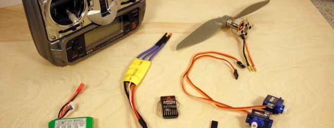
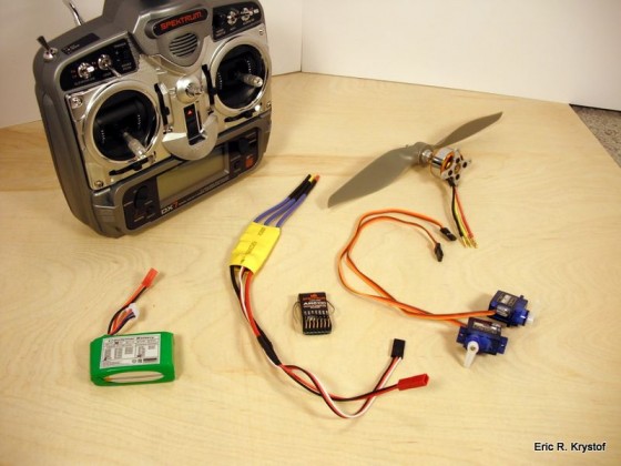
Here are the parts you’ll need for building this little monster. The combination of propellers, motor, ESC, etc. is important to note, this worked out well for our flying. Using a different Kv rating on your motor, or a different number of cells on your battery, for example, will yield different results. We also take ZERO…NONE…ZILCH…NADA responsibility for anything you do with these things. If you’re smart enough to build it, you’re smart enough to destroy it properly without hurting anything except the foam itself.
2600 Kv Brushless Outrunner Motor. A seemingly no-name brand is what we used, bought off ebay for a few bucks. Ours came with a simple metal motor mount and a prop collet. We used a prop saver instead of a collet. One thing to note is that these motors often list as having 3 mm shafts, but ours came with a 3.17 mm shaft, so measure first or get a couple different sized collets/prop savers. Ebay search
2 Tower Pro 9g Servos. Cheap servos, and cheap is good here. They’re more generic versions of Hitec H-55 servos. Ebay search
20C 1000mah 2S (2 cell) Li-Po Battery. You can go over 1000mah, but don’t go under that, or 20C rating. Ebay search
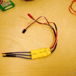
Minimum 25 Amp ESC – Our motor has a maximum current of around 20 amps, so the 25 Amp ESC is the minimum we want as we’ll be pulling that much on full throttle, plus power for receiver and servos. There are also ‘Volcano Series’ ESCs available, I’ve used those and they work out well. Anything over 25 amps is fine, but keep it around there for weight purposes. Ebay Search
Receiver/Transmitter Combo. This is where it can be a bit expensive. If you’re already flying helicopters or airplanes, you’ll probably be able to use a matching receiver for whatever transmitter you have. You can find cheap 3-6 channel 72 MHz FM transmitter/receivers on Tower Hobbies. We fly with Spektrum at the moment, so we already had a transmitter and I purchased a couple used receivers. Spektrum receivers for flying have a minimum of 5 channels, even though you’ll only be using 3. One of my flyers actually has a 6100 I took out of my E-Flight Blade CX2. I know what you’re thinking…but we’ll be recessing our receiver into the fuselage where it’s protected more than just dangling on the top, and it’s so small it’s a slim chance to get struck or damaged (and we’ve crashed these… plenty of times).
8×4 GWS Propeller. 8×4 worked well for our combination, and these props are cheap. If you’re comfortable with flying, you may want to use an APC prop instead of the same measurement. Tower Hobbies has props, just as your local hobby store should. The GWS props are easier to use with a prop saver, the APC props attach more easily with a collet, but they will work.
3.2mm Prop Saver. This mounts on our 3.17 mm motor shaft. The prop then mounts onto the saver, and rubber bands or O-Rings are used to secure the prop to the saver by wrapping the bands around two screws. This lets the prop get knocked off or bend away from the shaft in the event of a collision, hopefully without braking the prop. Search for 3.2 mm prop saver or hit your local hobby shop.
2 mm / 3,5mm / 4mm Bullet (Banana Plug) connectors. Whichever size you want will work, I used 2mm. Purely optional, you can hardwire the ESC/Motor connections with solder, but I prefer being able to unplug components. Buy in bulk from Digikey or an electronics supply store, or just a few at your local hobby store, or a place like RC Dude Hobbies
DOW Protection Board III – You can also use DOW Bluecor, either one will work. Bluecor has a light film on both sides, whereas the protection board only has it on one side. I couldn’t find Bluecor locally, but Lowe’s had protection board. You’ll be buying 50 feet at a time and it’s cheap, which means you can mess up… a lot.
Light Plywood – 1/8th or 1/16th inch – This is for building the firewall. I used 1/8th inch.
.77mm Piano Wire – Available from your local hobby store, .77 is the thickness we used. It can bend a bit, so you may want to go to 1 mm if you’re so inclined. It’s used to move the control surfaces (elevons) via the servo arm and control arm.
Control Arms – You can make your own with extra light ply, CA covered cardboard, an old credit card, etc. We used Dubro Micro Control Horns available at your LHS or Tower Hobbies here.
Mini-E Z Connectors – Used to adjust the piano wire control rod as it sits in the servo arm. Great for trim adjustment and frustration reduction. The control rod won’t go directly into the servo arm, instead it goes through the connector, and tightened with a screw, meaning you can make adjustments later without having to cut fresh wire. LHSor Tower Hobbies here.
Small wood screws – For screwing the motor into the motor mount, firewall, and foam fuselage.
5-Minute Epoxy – Your primary adhesive. Be quick, keep it thin, and don’t over do it.
Packing Tape – Colored if you can, but for the base assembly clear works fine. We like colors to help identify not only your flyer from others, but also orientation of your flyer when it’s way, way, waaaaaaay up there.
Gorilla Glue (optional if you want to fill in the cracks on the foam)
Tools
Solder/Soldering Iron
Cutting Utensil (X-Acto knife, foam cutter, razor blade, etc.)
Straight Edge / T-Square for measuring
The Plans
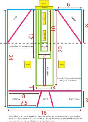
The plans for our combat flyer are very simple. It’s a delta-wing style foam-based craft (they call them ‘foamies’, no relation to rabies), so the entire craft is a flying wing. Two control surfaces at the trailing edge of the wing, and a stair-stepped fuseleage down the center. A simple rudder in the back and voila. There you go.
The plans are also available via PDF file.
 Mach One Plans (44.4 KiB, 1,066 hits)
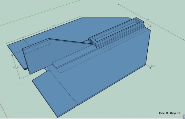
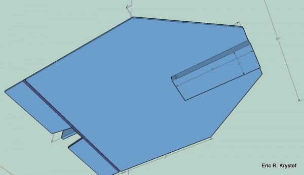
I also recently started playing with Google Sketchup – Here’s some 3D views:
First of all, let’s begin with a simple picture, the plans from the above looking down on your aircraft. Consider a 24 inch tall by 18 inch wide piece of foam. We’ll cut away the control surfaces (the parts of the aircraft that will rotate up and down) from the bottom of the foam and two triangles from the top. The green pieces indicate strips of foam we’ll be adhering to the center of the wing. This builds the fuselage and gives rigidity to the aircraft. The yellow boxes indicate general component placement.
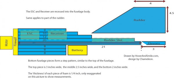
The side view shows how the ESC and receiver are going to be recessed into the fuselage for protection. Along with the general area to place the battery, it also shows the rudder and cutting line of the elevons. We’ve also included an angle on the leading edge of the elevons, which is 60 degrees sanded off the edge. The plans are as simple as that, and although the first construction may take some time, they become much more easy to build as you get comfortable working with the ingredients.
The Building
Now, the fun part. Here’s the pictures and video of our building process. A couple of notes, first…
- Don’t worry… It’s foam.
- It gets much easier and faster after your first build. You will build more at some point, they take a beating but in the end… a nice fresh foamie still flies better.
- Packing tape is your friend. We’ve gashed and broken these things down the center… A little packing tape and we threw it right back up in the air. Epoxy is useful too, for severe repairs, and 5-minute epoxy gets you back up in the air quick.
Oh, yes, and a special note from the Chameleon:
Enough of the theory… Let’s get moving.
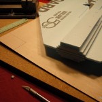
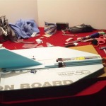
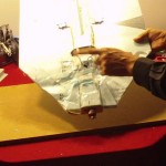
Here we have the pictures of Protection Board. Leto decided to inspect the quality for me, then decided to play hide and seek under the rest of the fan-fold foam. Nothing like having your ankles attacked when you’re standing up to take pictures.
Cat treats out to move him away temporarily, you can see how the foam will generally look after it has been cut out.
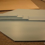
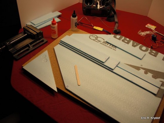
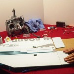
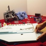
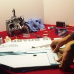
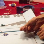
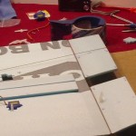
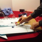
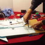
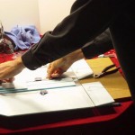
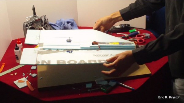
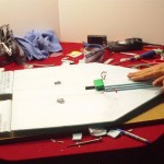
We already have cut out our main shape of the flying wing, we’ll build the fuselage on the top first by using four strips of foam. Note the base strip has the rudder slot cut out of it before we adhere it to our wing. With shorter and thinner pieces of foam, we get a stair stepped effect along the width and length of the fuselage. This is where we’ll be recessing our ESC and receiver. Using 5 minute epoxy available from your local hobby store, apply a very thin but even coat of epoxy to each fuselage piece and place it on your wing, lining it up with the front of your fuselage and centering it along the center of the aircraft. Keep some pressure with either hands or some books for a few minutes, making sure it’s lined up and has made a tight seal as the epoxy begins to cure.
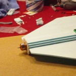
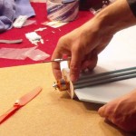
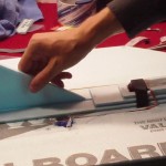
Now that we have the fuselage built on top and bottom, we’ll match up and sand our elevons. The term elevon is a combination of the words aileron and elevator, as we’ll be combining, or ‘mixing’ the functions on our delta wing. The elevons will be rotated up or down by our servos, which means we need to sand an angle on the leading edge of the elevon, otherwise the movement will not be smooth, causing the elevon to ‘bind’ against the trailing edge, or rear, of our flying wing. We’ll sand sixty degrees from the bottom of the elevon as seen here.
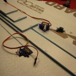
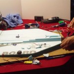
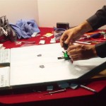
Our servos will actually be embedded into the surface of our wing. We’ll trace out around seven inches back from the trailing edge of the wing and about half an inch out from our fuselage. Then, we’ll cut that trace out, making sure there’s enough room for the servo arm to rotate. This servo came with a set of arms, so we’ll screw the arm on to the servo with the screws provided. This is where the piano wire will hook into, for the purpose of controlling our elevons. Notice we’re facing the servo so the cables can move along the fuselage and up towards where we’ll place the receiver. We can further recess the wires into the foam body by slightly cutting into foam (not all the way through). Then take a small screwdriver to open the slice enough to where the servo cables will fit into the foam. If you cut through, it’s no problem, just place some packing tape on the underside of the aircraft to seal it. We’ll mount the servo and cables with packing tape later, this is just a placeholder for now.
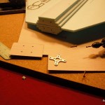
Our firewall is simple light plywood, you can easily place your fuselage pointing downward and trace around it. You’ll want to round the corners off the wood, as a corner jutting out beyond the foam can cause the firewall to rip off in the event of a crash. We then take the motor mount that came with the motor and trace four dots on both the wood and the fuselage. This is where we’ll mount the motor. We’re using small wood screws here, so we’ll actually drill four pilot holes into the fuselage slightly larger than the screws and pour epoxy into the holes. Once cured, this will help give the screws something to bite into when we actually mount the motor. After this is done, you can epoxy the firewall onto the fuselage, sanding the foam even if necessary, drill your holes, and mount your motor.
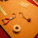
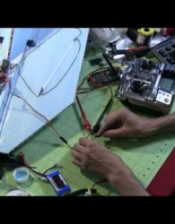
Your motors and ESC will often NOT have connectors attached. An easy way to solder the connectors is to hold them in a pair of pliers, put solder into the cup, and place the wire in the cup. As for the wiring, just make sure you match the right wires from the motor to ESC (black – negative, red – positive, yellow – signal). if your ESC doesn’t show colors on the end of it’s cables, you can tell which are which by looking at the color of the cables on the opposite side of the ESC, the middle ESC connector is always the signal.
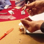
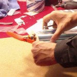
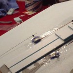
Let’s move back to our trailing edge for hinges. Packing tape will be used as our hinge, connecting the elevons to the trailing edge of our wing. Recall that we sanded a 60 degree angle off our elevons on the bottom side. Line up the elevon to the outside of your wing, and leave about 1/16th to 1/8th of an inch gap between the elevon and the wing itself. This, along with the angle cut, gives the elevon room to move without binding. Tape the top side first, then flip the elevon upward, and tape the bottom half. This way the bottom side of tape will actually follow along the angle and make contact with the bottom side of the wing.
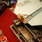
Now, we’ll take our piano wire, which is a little less than a millimeter in thickness and start lining it up with our servo and the spot on the elevons we’ll mount our control horns. We’ll cut a larger section of piano wire off to use until we’re done, then snip off the excess amount. Our control horns are Dubro Micro Control Horns, but you can easily look at the picture and make your own from light plywood or even an old credit card. The control horn is mounted into the eleven about half an inch back from the edge. Line up the control horn with the servo arm so our piano wire is relatively straight. The control horns are secured into the elevons using epoxy. Once secured bend a ‘Z’ in one end of the piano wire so it can twist and secure into the control horn.
As for the other end, we’ll use Dubro Mini E/Z Connectors, which screw into the servo arm. Then, the piano wire is placed into the E/Z connector and screwed tight with the supplied screw. This lets us make adjustments to the piano wire control rod without having to cut out a new piece. Simply loosen the screw on the E/Z connector, adjust, and re-tighten. You may need to use a drill to increase the size of the hole on the servo arm for the E/Z connector. With the servo arms centered upward, your goal is to have the elevons be level with the aircraft, as we’ll make fine tune adjustments later, so don’t snip the excess piano wire off yet, leave about an inch or so. Finally, we have the mechanisms in place to control our elevons moving up and down.
We then mount our servos by placing a strip of packing tape on the bottom of the aircraft over the holes we cut out earlier. Flipping it back over, place the servo into the frame so the bottom side sticks to the tape. Then simply place a strip of packing tape over the top of the servo and our recessed wires.
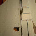
Now we’ll place our ESC and receiver into the fuselage. We’ll be cutting into our fuselage and picking out layers of foam at a time from the pieces of foam we adhered to the wing earlier. Since we used a thin later of epoxy, the pieces are easy to cut and pry out. You can use double sided tape for your ESC and Velcro for your receiver once you’ve dug enough out of your fuselage. Note how we cut out a small piece of the firewall for the motor wires to travel into our recessed area for hooking into the ESC.Of course, if you know your exact measurements before hand, you could just cut out the fuselage recession points before you epoxy it down….either way works.
After you’ve hooked up the motor to the ESC, you can do a simple primer test by hooking in the receiver, servos, and battery, making sure the motor turns and the servos are working correctly. For the servo tests, pulling back on the right stick should make both elevons move up. Up stick makes both elevons move down. Right stick makes the right aileron move up, and left aileron down, and left stick will make the left aileron move up, and the right aileron move down. Disconnect and we’ll continue with the final touches.
We mount our prop saver on the motor shaft. Given our measurement of the shaft of about 3.17 mm, we knew we would need a 3.2 mm prop saver for mounting. Prop savers are different from collets in that rubber bands or o-rings are used to secure the propeller to the motor. Either can be used, but prop savers have a tendency to let the propeller bend off the shaft, often saving the propeller in the case of a crash. You can use a rubber band or o-rings to secure the propeller by looping around the opposite screws of the saver. Use multiple o-rings if you go that route.
Now that we have all of our base electronics installed, it’s time to test the center of gravity. Simply place your fingers underneath the opposite corners where we have our CG line marked. It should balance at that point, if not there than ideally ¼ to ½ inch forward that line at most. If you need to adjust the ESC placement, simply move it up or down. It doesn’t need to be exact but should be close, given that we still need to mount our battery, which will serve as the ‘fine tuning’ point for our balancing.
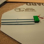
For the battery mounting, place a piece of tape on the bottom of the plane behind our fuselage, and attach adhesive Velcro to the taped area and the battery. Then check your center of gravity again and adjust accordingly. You can always cut a half inch or so at a time from your bottom fuselage to move the battery upward. Then, by using double sided Velcro straps, cut slits around the fuselage so we can secure the battery even further with a simple loop strap going up and over the center of the craft.
The last piece which we purposefully left off until the end is the rudder. Simply epoxy the rudder in place, where it fits into the rudder slot we cut out earlier and sits on top of the main wing. Let the epoxy cure and our construction is complete.
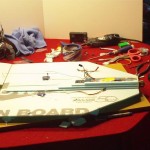
Apply packing tape over your receiver and fuselage and make sure things are secure, and keep in mind, if anything falls off, packing tape is your friend. Your repair box should consist of tape (your primary repair tool), propellers, rubber bands, and maybe a little epoxy. In the next video and article, we’ll examine fine tuning points, such as propeller size, amp draw, servo centering, and mixing.
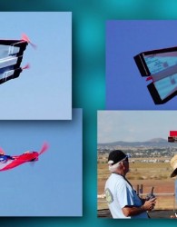
Our final construction of this one…and one I first flew and crashed a few times (oh, I just had to try some loops, pure pilot error on that one)…But you know what… It still flew, even with all that damage…That’s the great thing about these.
Thanks for checking this out, my father and I had a great time working together building our own, learning to fly them, thanks to Chameleon’s plans, parts list, and patience.





2 Comments
Josh
07/07/2011
Hi im loving the simple easy instructions on how to build a rc plane been as i havent made 1 before . But i was wondering i noticed you only had eilarons at the back , how do u manage to get them both to move the same direction to be used as a elivator as well as beeing used as eilarons?
Eric Krystof
07/07/2011
Josh,
Check this article out, it’s just what you’re looking for!
http://www.hoverandsmile.com/delta-wing-mixing/
No trackbacks yet.