Date posted: July 16, 2009
– Download DIY LED Helicopter Blades as PDF –
Make your own LED Helicopter blades for night flying!
I love LEDs. It’s the mini-electronics geek in me. Needless to say, it was one of the first modifications I wanted to make to my helicopters. I started searching for LED kits and saw Align cold light strings, LED flashing kits, strips, and then… LED Blades.
I was hooked right then and there… Discs of LED goodness as you’re flying your helicopter around. Then I noticed two things: price and availability. The price (typically over fifty dollars if not more for larger blades) and only having them in the size for larger helicopters (not so good for my CX3 or Blade CP Pro 2) set me off a bit.
I searched farther and found a four year old thread talking about making your own. A hobbyist had done some creative work which I attempted to duplicate and have reproduced with success. I took the idea and attempted to adopt it to smaller blades, as just like Saturday Night Live, I’m a not ready for prime-time player. So, here’s how I do it, in depth.
This is how I do it. I am sure there are ways to make this better, and I’ll note a few I have in my head for a later date. I’d love to hear of any improvements you’re thinking of.
The tools of the trade.
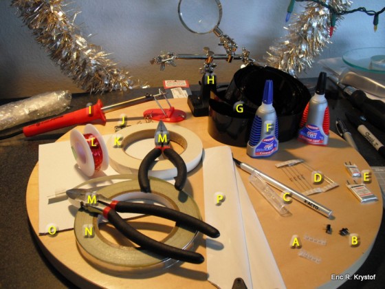
Tools for building LED Helicopter Blades
Here’s the rundown on the materials I use when I make these:
- A – LEDs – SMD (Surface Mount Device) LEDs are tiny. Fricken tiny. They’re used on circuit boards and enclosed electronic devices, like your cell phone. They’re also flat and light, making them great for blades. I use 0805 types (size classification), but any SMD LED should do. We’ll get more into LED voltage characteristics and circuit calculations later. Here’s two examples, but a search for “smd leds” in Google will yield lots of results. Needless to say: They’re tiny!
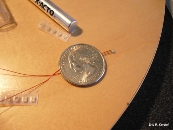
SMD LEDs are tiny. T to the i to the n to the y Tiny.
An LED already wired, with several others in the film strip packaging. The quarter is used as a size reference. It doesn’t light up.
- B – Switches – You can make a switch out of anything, but I prefer the real deal. It will allow you to turn the LEDs on for show, and off for charging the lipo. The ones I use are Mini-Slide Switches, with three pins (some have six pins, it really doesn’t matter)
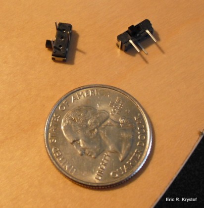
Switches for our LED Blade Circuit
- C – X-acto or hobby knife – One of your best friends for all sorts of reasons. It ranks right up there with Duct Tape.
- D – Resistors – LEDs will easily blow if too much current is passing through. You’ll need to add some resistors to the mix if you want to keep that from happening. Now, there are SMD resistors, just like the SMD LEDs, I just don’t have any right now but am looking to get some so that the circuit is a bit more aesthetically pleasing as well as keeping things ‘flat’.
Get it: Your local hobby store, radio shack, or
online.
- E – Li-Po Batteries – I use Lithium Polymer batteries primarily because of the weight and ease of use. Single cells with 80mah or 160mah are good enough, LEDs don’t take a lot of juice out. You will most likely need to purchase a lipo charger that can charge at a rate of .1 amps, as your standard chargers that come with Helicopter kits charge at a higher rate than these little guys can handle. Handle with care!
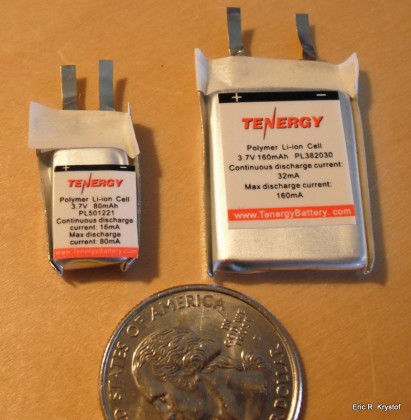
Single cell Lipo Batteries for the circuit.
- F – Glue. It’s sticky. Typical CA Glue – Which stands for Cyanoacrylate. It’s super.
- G – Shrink Tubing – We’ll use this to secure parts of our circuit and battery to the blade. You can use a high heat hair dryer or heat gun to shrink it. You’ll need to size out your blades to determine what works for you in terms of size and shrink factor.
- H – Weighted Alligator clips with Magnifying Glass – helpful for me, may not be for you.
- I – Soldering Iron – I use a standard 30W soldering iron with a pencil tip. I’m horrible with solder, but it works.
- J – Solder – Iron gets hot, solder melts. Hopefully at the right spot. Thinner solder is easier to handle, but the regular stuff that comes with the iron works.
- K – Masking Tape – It’s semi-sticky. Useful for steps ahead.
- L – Magnet Wire – It’s thin, and it’s wire. It’s for the circuit. This wire is insulated, so any connecting ends should be stripped with a little soldering iron heat or by scraping off the insulation with a dull blade (don’t cut the wire!).
Get it: Your local Radio Shack or Electronic Store, or online if you must, simple searching brought up
this
- M – Tools – Needle Nose Pliers and Cable Cutters. ‘Nuff said.
- N – Conductive Tape – Now, I use this to actually make the connections from wire to battery. You can solder the wire directly to the lipo tabs, but personally, I’m just not comfortable with that. If you are, great… But I’m not… yet. If you do go the soldering route with the lipo tab directly, normal materials won’t work on the aluminum tabs – you’ll need zinc flux and solder.
- O – Cardboard, thin piece. You’ll see why when we get the LED out. *ba dum dum tshhhh*
Get it: Take the cardboard box from that white elephant gift you can’t get rid of.
- P – Blades. This really should be self explanatory at this point.
- Q – Double sided tape. Almost forgot that. Not shown
GET TO WORK!
First things first. We need to know how much resistance to add to the circuit. Oh yes, it’s a circuit. Here’s a very simple schematic:
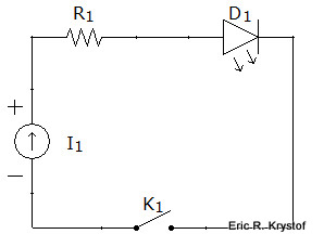
Our simple switched LED circuit
A lipo, a resistor, and a light emitting diode walk into a bar. The switch ducked.
So, we generally know by the lipo that we’re going to be able to pull enough mA for the LED. Here’s what you must know about your circuit, Lipo, and LED.
- Lipo – The voltage of a charged single cell lipo is around 4.2 volts. Generally you’re done flying around 3.6-3.8 volts, but oh my have I seen that vary between fliers. Some like it hot, some like it not. Regardless, that’s about what you’ve got to deal with. The lipo generally will have enough available current for any LED.
- LED – You must know the forward voltage of the LED. (i.e. The voltage drop across it). You must also know it’s maximum stable current it can draw in mA. These numbers should be given to you with the LED. Also, if you’re concerned about brightness, the higher the mcd (millicandela) rating, the more intense the light. The LEDs I’m using work fine for me, and they’re generally between 10-50 mcd. Next time I purchase some I’m going to go brighter. It’s like Tim Allen on Home Improvement. I want the Binford Ultra-Mega-LED-Burn-Your-Retinas-If-You-Get-To-Close-Lighting-System 3000.
- Circuit – You can run one and at least two LEDs off this circuit, but if you do so, you should run two LEDs in parallel. This means, split off the positive wire into two wires, each wire with one resistor and LED, joining the wires on the negative ends back to the switch and battery.
So, to determine the resistance you’ll need, head over to
LED Calculator. There I entered the data for my green LED:
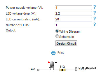
Figuring out our LED resistor values.
Looks like I need a 91 ohm resistor. Well, I have a 100 ohm resistor, so the LED won’t shine to it’s full potential, but it will be just fine for this case. We’re just holding it back one grade, it will still graduate, no worries there. You can always go over the suggested resistance value, but going under risks letting the smoke out of your LED, which makes it DOA.
The site is great – it even tells me the color of my resistors so I don’t have to look it up myself. I love that. If you happen to be color-blind, use an ohm-meter.
So, while my batteries are charging the soldering iron is heating up, let’s look at how we can solder the LEDs. They’re tiny, a soldering iron will just move them around, and we can’t alligator clip them easily at all.
This is a great tip I found through some forum searches, without it I’d be stuck using normal sized LEDs.
Here’s our little LED, sitting on the cardboard:
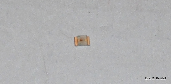
Tiny little SMD LED
There are some very important things to note in this picture.
- The LED has a lip. The two gold contacts are where you’ll be soldering your cables. So really you solder behind the LED, not on top of it.
- The LED has a negative contact marker. See the tiny green dot on the left side? That side’s contact is negative. Make a note of that, because diodes block current going the other way – if you wire it backwards, it won’t shine.
How in the hell am I supposed to solder THAT? I gave up when I first tried for about an hour on these little things. I figured, I don’t have the right tools, or my manual dexterity is that of a common house-plant.
Well, here’s that great tip I found. (Thanks
instructables!) We’re going to cut out on the piece of cardboard a little bed for our LED. Take your hobby knife and cut a very tiny square the size of the LED (exclude the length of the contacts, look at the LED itself).
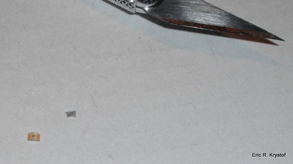
Building our SMD holder out of cardboard.
Now, we can actually flip the LED over and gently place it in the little cradle we’ve carved out. Just remember which side is negative! (On my picture, it’s the left contact, since I’m wiring behind the LED.)
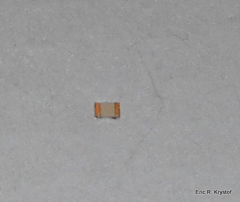
SMD LED in our little cardboard cradle for soldering.
So now we’ve built a cradle. The soldering iron is hot. Now, let’s prep our wire. Take a 6 to 8 inch length of our magnet wire and bend it at the half way point, making an open ended loop. We’re going to place the loop over our upside down LED like so:
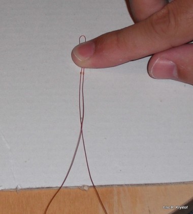
Placing our magnet wire over the SMD LED.
See how this is going to work? Our cradle stabilizes the LED, and our wire loop will go against the contacts. Take your needle nose pliers (unless you like holding onto hot wires) and use the soldering iron to melt the wire insulation/tin the wire in the spot we’ll lay over the contacts:
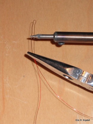
Burning off Magnet wire insulation.
I’m creating two LED blades at once here, so obviously I’ve two wires and two LEDs to do this to. Now, tape the loop down over the LED so the part of the wire we stripped of insulation lays over the contacts. This will make sure the wire stays in place. Then, solder the wire to the contacts. It’s still a bit rough to work with sometimes, but it’s a hell of a lot easier than trying to hold the LED down with the tip of a pen or screwdriver.
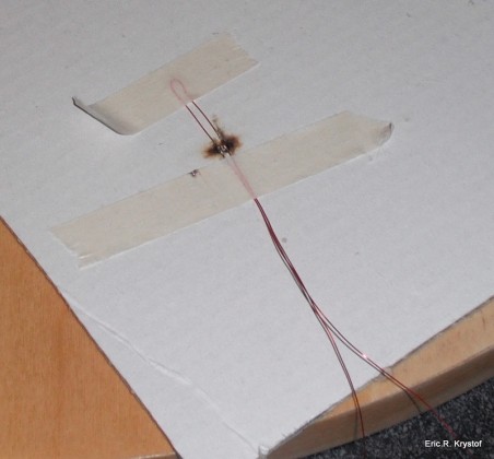
Taping down the bare wire over the SMD LED contacts.
Please don’t make fun of my soldering. I don’t make fun of your lawn.
Now that we’ve soldered the LED and wires, lift off the masking tape (any tape will do, but masking tape gives us just the right amount of adhesive to keep the wires steady yet still peel off easily) and clip off our loop so it’s wire->led positive terminal->led negative terminal->wire.
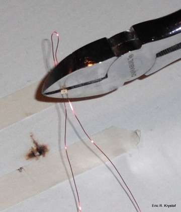
Snipping the excess wire loop away.
Snip, Snip. Oh.. um.. I can fix that. Unless you wanted a mohawk.
Next, if you place the free hanging wire tips against the soldering iron to strip the insulation there, you can quickly tap the wires against a battery to see if the connection is solid. Remember that we soldered backwards while the LED is upside down, so when facing me, the left wire is positive and the right wire is negative. Don’t do this with a terribly strong power source or even a small one too long unless you’ve got your resistor in the test circuit.
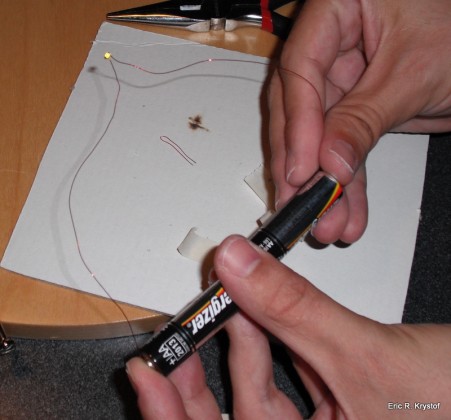
Simple AA battery test circuit for post soldering confirmation.
Now, I’ve two LEDs soldered to wires:
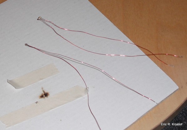
Leave plenty of wire hanging, you can always trim it later.
Next, we’ll get the resistors ready. You can use as much wire as you want, but I’ve grown comfortable with starting at the positive terminal of the battery going right to the resistor and then to the left wire on the LED. So, we need to solder the positive LED wire to the resistor. You can see the resistor held snug in the alligator clip.
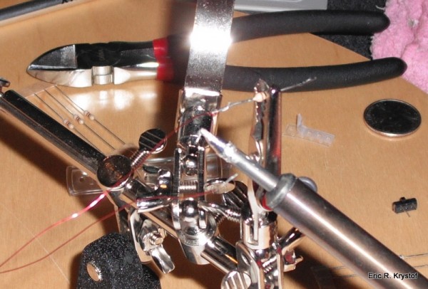
Using a third-arm sometimes makes it easier.
Our resistors are part of the LED connection.
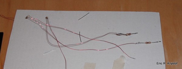
Adding resistors into the circuit.
Resistance isn’t futile, it’s mandatory.
Now for some more soldering. Here’s the switch. We’ll be mounting it behind our battery, so as you see the pins in the picture, we’ll be removing the left pin (twist or cut it, they’re easily removed), the middle pin will attach to the negative wire on our LED, and the rightmost pin will connect to the negative terminal of our battery.
For some reason I got into the habit of using red magnet wire for my LEDs and green magnet wire for the switch. Ah well, tis the season. Solder two green wires to the switch terminals, leave about four to five inches of wire based on the length of your blades and LEDs.
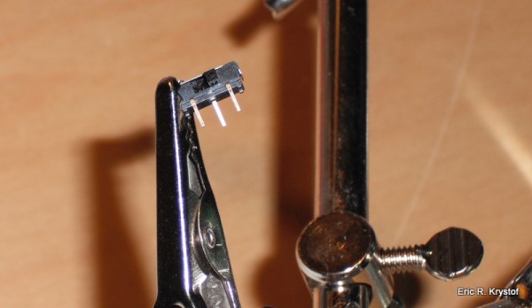
Adding the switch to the circuit.
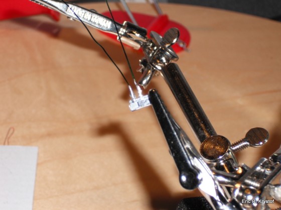
If you're not a fan of soldering, this isn't going to be fun for you.
Note that the switch has been… switched upside down in this picture.
Now, we’ll mount our Lipo and switch to the blade. By the way, I’m using flat bottom blades for this, I have not tried this on symmetrical blades, and since I don’t do 3D moves yet, I don’t know how well this rig would hold up.
Attach some double sided tape to the back of the lipo for added security and glue the switch behind the lipo, bending the wires at the switch terminals to the right (negative) side of the battery. I use more of a CA Gel on the switch, but whatever works for you.
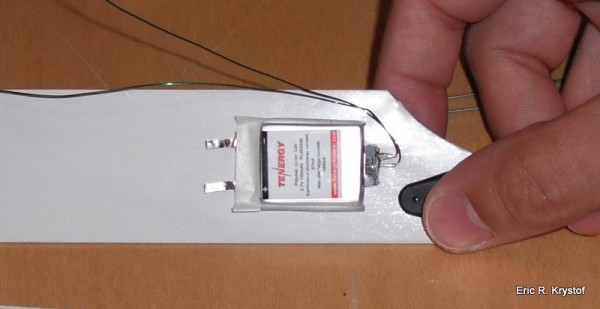
Placing the battery on the root of the blade bottom.
We’ll then secure the battery, I’ll use some heat shrink tubing, wrapping around the battery but leaving the switch and terminals open.
Before the heat:
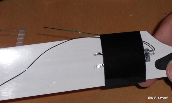
Shrink tubing over our battery, leaving contacts exposed.
After the heat:
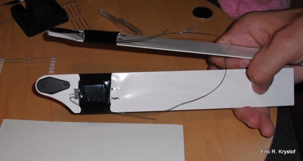
Example view of a nearly completed circuit.
Now, we have the general idea as to how the circuit is going to go. The positive terminal of the lipo leads to the resistor which we soldered to the postive wire of the LED. The negative wire connected to the LED connects to the green wire which connects to the middle switch terminal, and the right most switch terminal connects to the negative terminal of the battery, completing the circuit. Here’s a very rough layout before mounting the circuit:
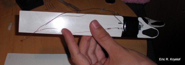
Example view of a nearly completed circuit.
Follow along and spot CA the wire along the blade, letting each spot dry some before moving on to the next. I don’t actually glue the resistor down at all. We continue on the blade until we can bring the LED to a side of the blade, sort of ‘bending’ it outward. This is a pure point of customization… If you secure the LED to face out from the side of the blade, you’ll see the LED whether below or above the helicopter. If you secure the LED on the bottom flat side of the blade, you’ll only see the light when the heli is above you. Up to you, but based on which LED is mounted which way, it could help in orientation during night flying.
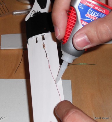
Gluing the wire to the blade bottom.
Here’s how a completed blade looks after the glue. Yes, I know I could have made the positive LED shorter, but at the last minute I decided I wanted this LED closer to the center of the blade. (That sounds so much better than I screwed up, doesn’t it?)
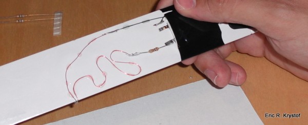
Little bit of wire left over… Ah well. Snip it next time.
Here’s where you’ll need special zinc flux and solder for the lipo connection. Actually, if you’re doing that, you should solder some wires to the lipo before you mount it to the blade. I haven’t handled that part yet, so I’m using some conductive foil tape to ‘wrap’ the resistor to the positive terminal and the remaining green wire to the negative terminal.
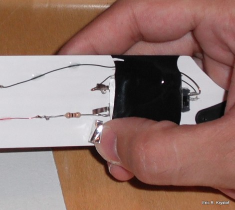
I didn't want to solder the batteries directly. Some simple foil tape retains connectivity if you don't want to solder battery contacts.
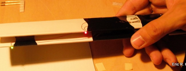
After the glue has set, I shrink tube a bit along the blade, covering the resistor and a few solder spots. I also put small strips near where the LED bends over to the side of the blade. This is also a great way to perform blade tracking with a laser pointer, since I now have one blade that has a darker spot than the other, it’s easy to tell which blade is tracking higher or lower. After that, switch it on and you should see some lights!

SMD LED Blades wired up and lit.
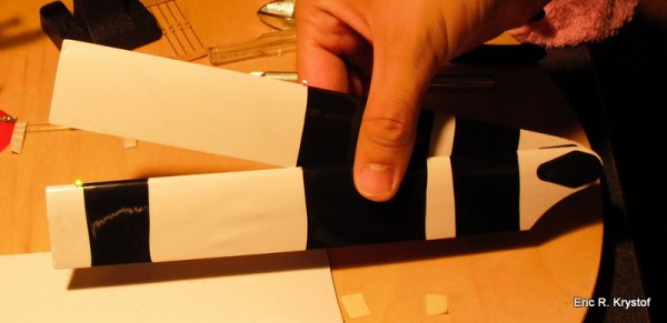
SMD LED Blades wired up and lit.
Now, you’ll have to balance your blades and make sure they track. The usual business. Once that’s done and the blades are on the bird, let it fly!
I hope you enjoyed reading this article as much as I did writing it and experimenting with self made LED blades.
I’ve been running one heli with these blades for a while, and haven’t noticed any real issues (as long as I don’t crash). To charge the battery, just switch off the circuit and connect a charger to the positive and negative terminals of the battery itself.
Drop me a line if you’d like to discuss any alternative designs or improvements, I’m looking to make it better all the time.
Tags:
blades,
electronic-circuits,
featured,
LED,
night flying,
SMD






2 Comments
Phill
06/07/2011
great job and entertaining too:)i did’nt realise they were that small , i would like to try and use the flight battery for power so im gonna have to do a bit of homework on the swashplate contact design and if i go for the mSR(just got to get round the mrs XD) i’ll try and wire from the canopy LED to the blades if poss.
Eric Krystof
06/07/2011
Thanks, Phill!
So, as you can see, I’m using the standard batteries attached to blades method. I don’t actually come near the swashplate or handle contacts there. Each blade is powered by itself. It works, but clearly there are some things that I’d like to try at some point, and good luck to you if you get there!
Removing batteries from the blades does have a safety benefit of not having a Li-Po battery as a projectile, and others have asked me about a contact under the swash plate for completing the circuit instead of batteries. This would also allow you to, just as you stated, tap into the flight battery itself, which for the mSR would be a complete necessity given how small the blades are, the LEDs alone would be all you can put on the blades directly.
So, I don’t have a working model of a swashplate contact design, but it comes down to a place for the negative (ground) wire to hit the chasis or main shaft, and then the positive wire would come down and contact like a brushed motor against a metal swashplate ‘ring’. So far, I’ve considered a non-hole-punched circuit board as the contact ring as it’s easily cut to fit whatever size you want. Then it’s just figuring out brushes and on the mSR, where you can attach the negative wire too, as I think the mSR is pretty much plastic on the rotor, perhaps some small metal rods can be attached.
That’s the big hurdle. As far as power from the flight battery up to the the chasis and conductive disk on the swash plate, some simple wire splicing can be used for the mSR’s battery pack. With battery packs bigger than the mSR that have separate balance plugs, I’d vote for tapping into the balance plug directly.
Let me know if you come up with a working model for a brushed contact plate around the swash, I’d love to post an addendum on here showing how you did it!
No trackbacks yet.