Date posted: October 10, 2009
- Introduction to Basic RC Aircraft and Helicopter Circuits
- LiPo Batteries
- Electronic Speed Controllers
– Download Introduction to Basic RC Aircraft and Helicopter Circuits as PDF –
I decided to stretch my video editing wings a bit and whipped up a basic introductory video to the common RC circuit components.
Clearly a very high level introduction, but useful to describe all those neat whiz-bang type of things that make this hobby work.
Here’s the narration, for better or for worse, along with the video:
Welcome to a Hover and Smile presentation of basic RC electronics. When I first started out in this hobby earlier this year, I had no idea what a servo really does for a helicopter, let alone what an ESC was or why I needed one. Therefore, I put together this video to show the basic elements used in almost any RC helicopter and airplane setup in regards to electronics.
It’s important to note that although the components themselves can be guaranteed to change from model to model, the basic concepts remain the same. Therefore, this video can help a relative newcomer understand exactly what plugs into what and more importantly, why!
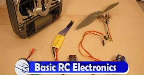
So, here we have the basic components to our current work in progress, a flying wing design combat airplane. Our cast, in no particular order, consists of:
A power source – in this case a Lithium Polymner (Li-po) battery
An electronic speed control (often abbreviated as an ESC)
A receiver – in this case a Spektrum 6100
Servos – in this case two Tower Pros weighing in at 9 grams.
A motor – in this case a brushless outrunner with propeller attached.
Last but not least, our transmitter, a Spektrum DX-7.
Keep in mind that this is a very high level introduction to the components as a whole, there is always more detail that we’ll cover in later segments in regards to each piece individually.
Li-Po Batteries
Li-Po is the common abbreviation for Lithium Polymer. A huge advancement in battery technology for RC enthusiasts, Li-Po batteries allow for more power with less weight than other battery types.
Li-Po batteries have a single common denominator of voltage called a cell. When fully charged, a li-po cell stores 4.2 volts. More power is obtained by adding more cells to the circuit. Therefore, a 2S (2-cell) lipo would have up to 8.4 volts fully charged. 3S would have 12.6 volts, and so on. Typically, a cell is referred by it’s nominal voltage of 3.7 volts per cell, not its peak voltage. The other two major factors in li-po batteries are discharge rate and milliamp hours (mAh). Discharge rate, measured in charge value C, determines how much amperage (current) can be pulled from the battery at one time. This helps determine how much of a ‘punch’ your battery packs.
The capacity of the battery is measured in milliamp hours, which determines how long your battery can supply power until it needs recharging. The more mAh, the longer your battery can supply juice.
Li-Po batteries don’t have the exact same memory issues you may find in a Nickel Cadmium battery, but they do have some limitations. They must not be charged over 4.2 volts per cell, and discharging them too low can result in a battery that can no longer charge properly. Charging or discharging a li-po battery too fast can lead to overheating, puffing, and explosion. Suffice it to say, if you read the instructions and treat the batteries with respect, you’ll have no problems. Given that they are more volatile than regular household rechargeable batteries, enthusiasts often use metal boxes or li-po bags to store the batteries while charging or for long-term storage.
ESC–Electronic Speed Controller
The ESC Component of an RC circuit is used to connect your batteries power to both your motor as well as your receiver and servos through a BEC – Battery Eliminator Circuit – typically contained within the ESC itself. The ESC supplies the different signals and power requirements of both the true electronic components and the motor.
The ESC input connection is from the battery itself. The outputs are directly to the motor and receiver. The throttle channel on your receiver, in our case channel 3, takes the output connection from the ESC. This will then supply power to the servos through the other receiver connections and other electronic components (such as lights or gyros).
An electronic speed control is rated in amount of Amps that it’s circuitry can withstand. The proper ESC for one circuit may not be enough for another, and typically power needs and motor capability often drive which ESC is right for which circuit. A good rule of thumb is to go 5 to 10 amps higher on the ESC rating than the motor itself, allowing for the other electronics in a circuit to receive power as well as any ‘bursts’ which may occur when pushing your model to the limit.
Another feature of ESCs is that many of them are programmable in some way, via your transmitter or data cables. A typical programming example is LVC – Low voltage cutoff – if the power supply runs below a certain voltage you’ve programmed for, theESC will stop supplying power to the motor so your li-po doesn’t discharge too far. The cutoff can often be set to a ‘hard’ or ‘soft’ value – where the motor can shut down fast, or gradually lose power. Soft cutoff is preferred when powering helicopters, as airplanes can typically glide in for a landing.
Receivers
The receiver is the component which lets you fly your craft without having a long line of wires connecting it to you. Receivers and their other half, transmitters, often run at government regulated radio frequencies such as 72 MHz or 2.4 GHz. Not only does your receiver and your transmitter have to properly match in radio spectrum, but they also must match in technology. Companies such as Futaba, Spektrum, Esky, and more supply their own pairs of receivers and transmitters. One companies transmitter is never guaranteed to work on a different companies receiver.
The receiver takes inputs from the transmitter (be it from stick movement, switches, or dials) and relays that to the appropriate component in your circuit. Pushing your throttle up on your transmitter sends a signal to your throttle channel on the receiver, out to your ESC, and then out to your motor, changing the speed accordingly. The same goes for your servos and other electronics. Pulling back on your transmitter cyclic would send signals to your helicopter to change the angle of your swash plate via a servo, causing the helicopter to move back towards you.
Receivers often have a specific number of channels associated with them. A channel is simply mapped to one specific element of your circuit, be it a motor or a certain servo. The more channels that a circuit is using, the higher caliber transmitter and receiver pair you’ll need. Simple two or three channel helicopters for example only control motor speed, yaw, and limited forward flight. Complex helicopters, capable of inverted flight and loops, will require at least six channels.
Some receivers are actually combined with an electronic component called a mixer, which, like a soundboard, takes incoming transmissions to your receiver and mixes them into multiple channel outputs. This is often the case with ’4-in-1’ units, which combine receiver, gyro, speed control, and mixing into one physical component. Without an on-board mixer, you’d need a programmable transmitter to handle any mixing. Regardless of being on-board or handled by a programmable transmitter, mixing is a complex topic in its own right, but often handled for you in beginner level stock configurations.
Servos
Servos are small motors controlled via signals sent from your receiver. These little guys, with the attached ‘servo horns’ – the white plastic connectors in our example picture, manipulate the various control surfaces on your aircraft or helicopter. For airplanes, a servo may pull or push an elevator, aileron, or rudder control surface back or forth, affecting the flight dynamics of your aircraft. For helicopters, servos can control the angle of your swash plate, which changes the angle which the blades rotate, affecting movement. They can also control tail rotor blades and pitch of your helicopter blades, not only affecting lift, but also allowing for 3D maneuvers such as inverted flight, loops, and rolls.
In general, the size and weight of a servo are chosen based on the type of aircraft you’re flying. Large scale helicopters and airplanes will require larger servos with plenty of torque to handle movement of your control surfaces. As with anything in our example circuit, there are many different types of servos to choose from. RTF – Ready to Fly kits have servos already attached and configured for beginning flyers.
Servos are often designated as digital or analog. The primary difference is related to how both servos work with pulses sent from the receiver. Digital servos are meant to handle more pulses per second from a receiver than an analog servo, allowing for faster and more precise movement. Often times digital servos are required for advanced acrobatic techniques, whereas analog servos are typically well-suited for beginner level craft.
Motors
The motor is the essential moving part that either spins a helicopter blade or aircraft propeller. Once again, as we have many different types of circuits and craft available, the choice of which motor to use is a necessary consideration.
Without going too deep into the actual inner workings of motors themselves, RC motors are often characterized with the terms outrunner vs. inrunner and brushed vs. brushless.
Outrunner motors generally have a lower Kv rating than inrunner motors. The Kv rating, known as RPM per volt, relates directly to how fast the motor will rotate given a specific power supply input. The higher the Kv rating, the faster a motor will spin. Even though outrunner motors may have a lower Kv rating, they supply more torque. The choice between one lies in a deeper understanding of the specific craft at hand, or by asking your fellow enthusiasts and going with the flow.
Brushed vs. Brushless – Brushed motors, like the name says, use metal contacts internally called brushes. Brushless motors obviously don’t use brushes, and work by instead powering up internal coils in sequence, causing a magnet attached to the outer shaft to rotate. Technicalities aside, brushless motors generally have more power and last longer than brushed motors, and are therefore preferred. However, for very small craft or cheaper ready to fly kits, brushed motors are an economic alternative.
Transmitters
Directly talking to the receiver in our circuit, transmitters are all about you becoming one with your aircraft. With sticks, switches and dials, transmitters allow your hand inputs to send signals to the receiver, causing the servos in your circuits to move, your motor to turn faster, or even turn lights on or off.
Many RTF kits come with transmitters along with the craft itself, and are often only suited for that specific type of craft. Low-end Ready to Fly Kits often include transmitters that are only somewhat flexible in terms of programmatic capabilities to control a different aircraft.
As you become more engrossed in the hobby, you’ll find yourself purchasing a programmable transmitter, which allows you to control multiple aircraft without the need for one transmitter for each airplane or helicopter you own.
We here at Hover and Smile hope this brief introduction helps shed some light on the most basic components of RC electronic circuits.


