Date posted: May 15, 2010
- Introduction to Basic RC Aircraft and Helicopter Circuits
- LiPo Batteries
- Electronic Speed Controllers
– Download Electronic Speed Controllers as PDF –
Electronic Speed Controllers (ESCs for short) bridge the gap between your battery, motor, and receiver. The ESC takes input from your receiver (while often supplying power to your receiver) to drive your motor with power supplied from the battery. So,ESCs have three connection points – two wires for your battery, a set of wires for your motor, and a set of wires for your receiver.
This article and video will explain how ESCs typically work, looking at an ESC from a power standpoint, and a little bit on programming. Nothing too low level for this round – we’re really looking at points to consider for the power requirements of your circuit and the ESC that best fits your needs.
Types of Electronic Speed Controls
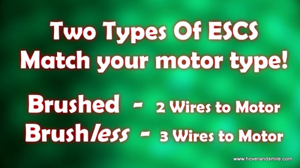
There are two primary types of ESCs, and they MUST match the type of Motor you’re using. It’s quite simple – Brushed motors require brushed speed controls, and brushless motors require a brush_less_ speed control. The big difference here relates to the motor. Not to get to deep into the making of motors, but let’s just say that since brushed motors rotate through ‘mechanical commutation’ – where there’s a commutator and brushes that drive your motor to turn, a brushless motor’s commutation is done via electronic signals from your ESC, which allows the motor to be just that – brushless. This is why brushed ESCs have two wires for the brushed motor, and brushless ESCs have three wires for the brushless motors.
Battery Eliminator Circuits
Either way, if you have a brushed Motor/ESC pair or brushless Motor/ESC pair, you can use the same receiver and battery for either setup. However, there is one thing to keep in mind when you’re choosing a speed control. Whether or not there’s a BEC – Battery Eliminator Circuit – embedded in your speed control or if you need to purchase one separately.
So what’s a BEC? Well, receivers need power too, but they typically need somewhere in the range of 3 to 9 volts (depending on your receiver) to get power. If you’re using a 3S battery (11.1 volts) – you’ll easily fry your receiver if you plugged the battery directly into it. We’re talking the release of that magic blue smoke. That’s bad.Crossing the streams bad.
One option is to simply have a separate battery pack that powers the receiver and servos (which typically get power from the receiver). But… who wants to carry another battery pack around? Receivers and servos don’t take a lot of power for your smaller park flyers, carrying around a second battery pack to power your receiver and servos is cumbersome and only to be used when necessary.
A Battery Eliminator Circuit drops down voltage for your RX!
Enter the BEC. BEC’s are basically voltage regulators. They take a high input voltage and output a lesser voltage. This is what lets you plug in a 11.1 volt lipo and only let 5 volts out to your receiver and servos. Even then, there are two types of voltage regulators that BECs typically employ – linear and switching. Voltage regulators need to drop the voltage somehow. Linear regulators do this by dissipating heat. That means it will get warm, even hot, as it steps the voltage down to a level the receiver can handle. A switching BEC, on the other hand, rapidly cycles the power on and off, which makes it generally more efficient, as it doesn’t have to dump power in the form of heat.
You could dive more into that detail, but just know that those are your two types of regulators – which means two common types of BECs. Where you use one over the other often comes down to some gritty electronic details, so mostly… just make sure you have one IN your ESC or you get one to wire TO your BEC-less ESC.
A lot of ESCs you’ll find have a linear BEC embedded inside the shrink wrapped package. This works well, it’s all together and you have less wiring to worry about. However, let’s think about what we just discussed about heat. If I have a speed control that supports 6S batteries, that’s 22 volts that the linear regulator has to step down to 6 volts. That’s a lot of power a linear regulator has to dissipate as heat compared to say a two or three cell battery (7 – 11 volts).
In or Out?
This is why you’ll typically see higher capacity ESCs have a switch mode BEC or nointernal BEC at all. When you don’t have a BEC embedded with your ESC, you’ll need to supply one yourself and wire it in your circuit. What typically happens here is that your battery connects to both your ESC and external BEC, and your BEC outputs to your receiver for power, and your ESC outputs to your receiver for throttle signalONLY. (When you have a BEC embedded in an ESC, your throttle control and power to your receiver are combined into one set of wires)
Once again, this is typically necessary for larger RC circuits, but it’s not uncommon to see an external BEC in smaller circuits as well. A lot of your park flyers or 200-400 size helicopters are using 2 or three cell lipos, so it’s not often a consideration. Regardless, there it is for the time you decide to step up your circuits to larger voltage and amperage needs.
So now we’ve covered the two types of ESCs – brushed and brushless, and BECs – external and internal, and also switching vs linear.
Choosing the right speed control (for you) from a power standpoint
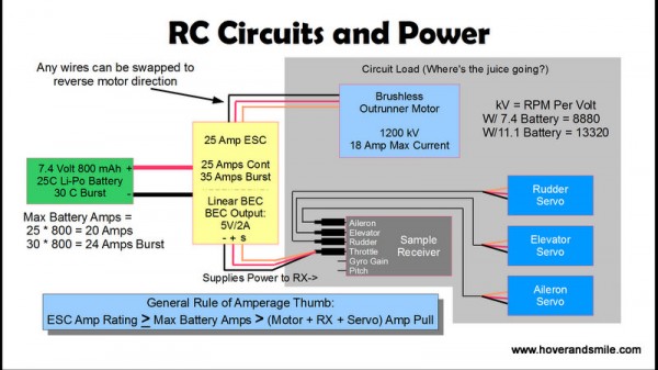
In your entire RC circuit shown here, you have a constantly changing equation you must balance to make sure you don’t over tax one part of your system. However, since the ESC is typically taking all of the current from the battery, it needs to have the highest amperage rating over any other part. You can always go higher in amperage on an ESC to be safe, but you can never go lower. But what is ‘lower’? Lower than what?
Lower than the maximum amperage you’ll be pulling through your circuit. This is defined by the load on your circuit – which means everything that uses power – your receiver, servos, and motor. The combined amperage pull from those components combined MUST be less than your ESC’s rating.
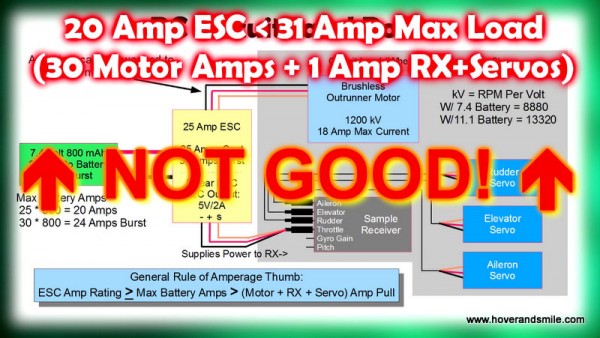
So look at this example here, if you have a motor that is rated at 18 amps maximum current allowed, and say the servos and receivers will take no more than 1 amp, you could get away with a 20 amp speed control. However, I like to play it a little safe for a few reasons, and would go with a 25 amp speed control. Remember, the ESC rating can always be higher than you need, at that point it comes down to an issue of weight (higher amp ESCs weigh more, of course). One thing I generally keep in mind is that if you crash and your throttle is up, this can cause an amp spike through your circuit – so a 25 amp ESC would have a chance to handle that better than a 20 amp ESC given the power requirements of this circuit. (We also keep that in mind with plane-on-plane combat, where your prop is a weapon.)
Of course, we need to make sure the battery can safely discharge that many amps, and in our case, it can. 20 amps continuous, 24 amps burst, so we’ll be safe here. That’s why the general rule of thumb is ESC Amp Rating must be greater than safe battery discharge, which must in turn be greater than load on the circuit – RX, servos, and motor amp pull combined.
Now you can see why a watt meter is so nice when you’re calibrating your circuit – you can rev up the motor, move all the servos, and use the watt meter to see how many amps you’re really pulling through your circuit.
If you change any parts of this circuit out, you need to make sure the rest of the circuit can handle it. Say I put a bigger motor that can pull 30 amps. Well, now I need upgrade my ESC and battery to handle the extra load. Always keep that in mind. Change one part of the equation, and you need to balance it out.
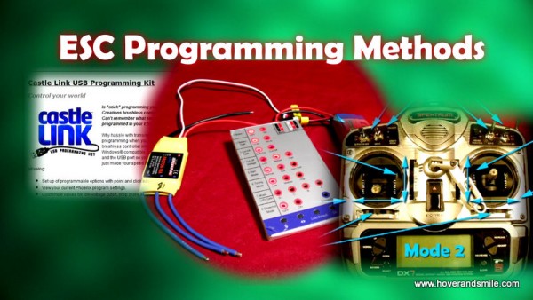
Speed Control Programming Methods
ESCs often have different programming options that allow you to customize how theESC works. There are simply way too many brands of ESCs out there to cover in this article, but we’ll look at a few of the most common methods and options for programming an ESC.
ESCs can typically be programmed through three different methods:
- USB programming kits (Castle Creation’s Castle Link is a good example of this)
- Programming Cards – Small cards or hand-held devices that you plug a 6-7 Volt battery pack and ESC into, pushing buttons to change LED options on the device.
- Throttle Stick Programming – Using your ESC and receiver, you can use the throttle stick on your transmitter to choose options through a set of audible beeps.
Also, keep in mind, that different brands of ESCs can’t all be programmed the same way – you’ll need to read your ESC’s instructions and learn how to program it and which programming methods it supports. Each ESC maker is different.
Speed Control Programming Options
Clearly, programming an ESC is going to be another video and topic, and you can see from this list that some options are more tedious and error prone than others. Now that we’ve looked at how an ESC could be programmed, let’s look at some of the most common programming options. Once again, since ESCs are so different from factory to factory, some ESCs have spiffy auto detection for things like how many Li-Po cells are connected, while others require you to manually set the options.
This list of options is not necessarily related to a specific ESC, it’s a sample of some options your ESC may support. ESCs often also have ‘default’ settings for these options.
- Battery Types – Often defaulting to Li-Po, but can be changed to support NiMH or NiCd batteries.
- Low Voltage Cutoff – Extremely useful for Li-po batteries – this determines when your ESC will cut power to your motor, and whether or not it does this soft or hard.
- Low Voltage Cutoff Level – Protect your Li-pos by telling your ESC to power off your motor if your Li-Po pack goes down to 3 volts per cell, 3.2 volts per cell, etc.
- Brake Setting – Enabled or Disabled – This means if you reduce your throttle, does the ESC tell your motor to spin freely until it stops or to stop turning immediately.
- Start Up mode – Soft or Hard – Hard is often used for airplanes, Soft is often used for helicopters. It all comes down what you’re flying – this deals with how fast the ESC lets your motor accelerate.
- Timing – Low/Medium/High – an advanced setting for brushless motors, related to the signals sent from the ESC to the motor. You can generally use the default, but research your motor and ESC preferences together to know how they should fit.
- Throttle Range – Auto or fixed – This often depends heavily on the model – helicopter or airplane, and deals with how the transmitter throttle stick corresponds to the output of your ESC to your motor.
That’s a taste of your most common ESC programming options, which we may cover some day in a more dedicated article to ESCs. In the end, though, we’ve covered the high level basics but most importantly – the power considerations in choosing the rightESC for the job. Keep it’s amp rating higher than any load you’ll have on your circuit and you’ll be all set!






4 Comments
FinalFrag
07/07/2011
Thank you for doing this series. Video + annotation makes it even better, I can watch the video and use the annotations to look something up later on.
It doesn’t show in the amount of comments here, but you deserve respect for taking the time to do this for beginners like me. I’m just getting into the hobby and these 2 video’s have helped me a lot already.
I see it’s already a while ago you did this video, are you still planning on doing the other parts of the circuit? I would love to have more like these videos to learn. There is a lot to be found on the internet, but it’s all explained in a harder way.
1 little comment though…. try to speak a bit slower. You better make the video longer than to cram everything in a short one.
Hope you plan to do more videos in this series!
Eric Krystof
07/07/2011
FinalFrag, you’re very welcome. I’m glad you’ve enjoyed the series, and I also thank you very much for the annotation and video comment, I’ve thought of dropping it for just videos, which would speed some things up, but I’ll keep it the way it is for what it’s worth
I still am planning on future parts. I have roughly four videos on the BEC part of the ESC alone, and then I’ll come back to the ESC for detail on programming them. It’s just taking longer than I anticipated.
I’ll definitely try to slow it down!
Greg
07/07/2011
Great videos and very informative. Thank you, I needed that!.
I used to fly glow-plug airplanes 20 years ago and gave it up as flying fields got further away. Now with electrics being so advanced and electric only fields closer, I feel I need to return to school on using electric motors and perhaps converting my dozen idle aircraft to electric power.
I don’t think you need to speak slower because I just pause the video and/or backup to make notes or review what you said.
What I’d like to see are answers to real-life issues. For example, what will a 25C battery do to performance vs. swapping it for the same mAh capacity battery but with a 16C rating? Also what happens if you use an ESC that is 10 amps or 15 amps over what you need? Will you burn out your components?
Eric Krystof
07/07/2011
Greg,
Thanks for the compliments. Tonight at our club meeting I’m giving a presentation on the basics of electric flight from a ‘I flew glow before, so I know what servos are, just tell me the differences’ standpoint. I’ll do a film/article version of it based on the presentation and kick up the rc power series a bit.
As for the real life issues, I’ll make note of these and see what I can show ‘safely’ from a video standpoint.
As for a quick non video response – even though C ratings are partially marketing gimmicks, in general, a higher C rating has lower internal resistance (I’ll have to include how that can be measured, but just from a theory standpoint go along with it), so it can provide more amperage to your circuit. Swapping out a lower C rating battery would give you less power, and if low enough, cause enough stress on the battery to make it get warm and ‘puff’ – which is bad for the life span of your battery, and if you get it too hot and puffy, it’s time to rip it out and let it sit on the cement for a while, because it risks venting.
As for the ESC rating – you can go ANY amount of amps over what you need. The ESC is your ceiling, it won’t burn out from being ‘under-used’. You can raise it as high as you want, but you can only lower it to the maximum current that goes through your circuit. Or, in a real life scenario, until the ceiling hits your head when you walk into the house.
The only reason we try to keep the ESC close to (but still always above) our max amperage is because bigger ESC’s weigh more and are more expensive. Hope that helps!
No trackbacks yet.